- Home
- Products
- Three phase Separator
- Three-phase Separator
ProductsPRODUCTS
Featured products

Contact Us
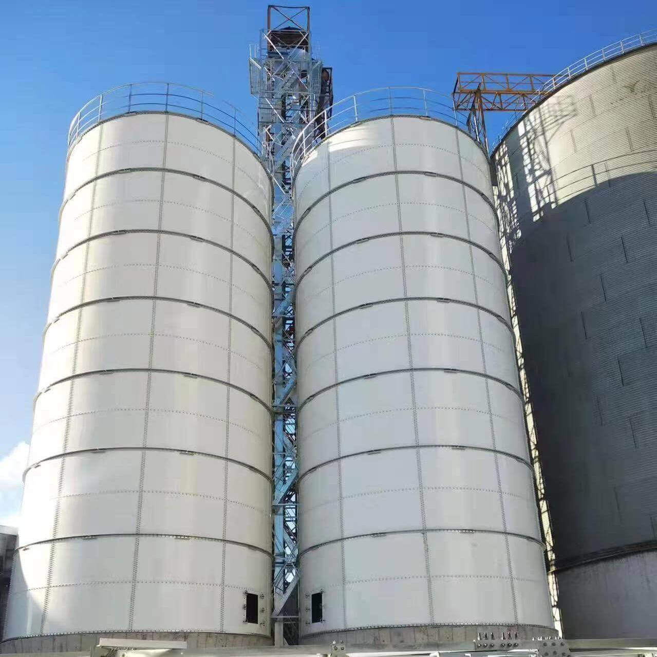
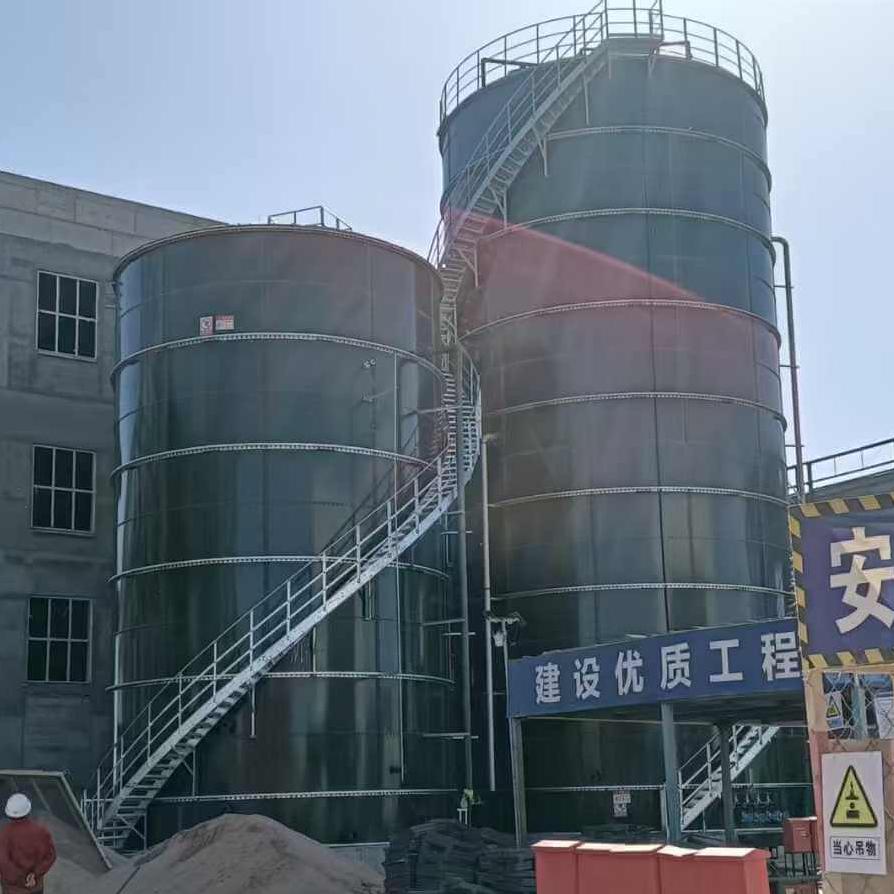
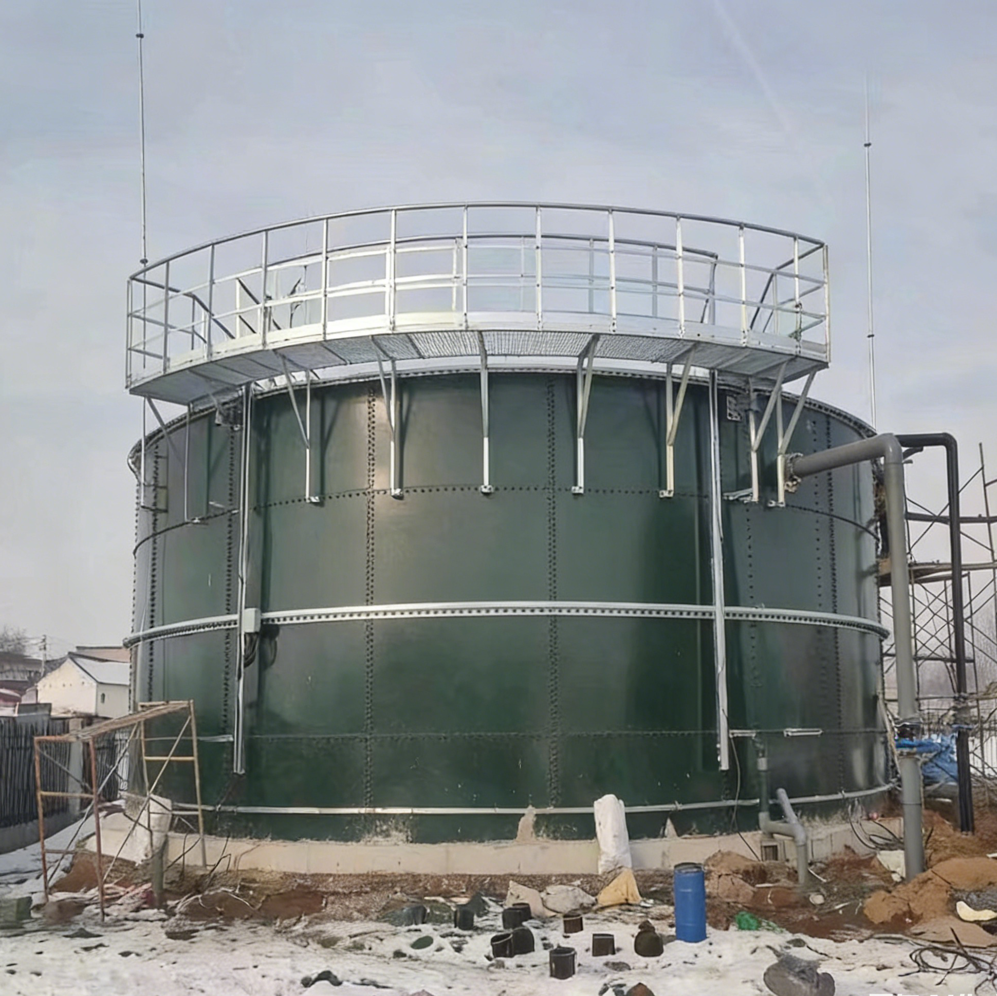
In today’s pursuit of green and low-carbon development, efficient and energy-saving wastewater treatment technologies have drawn much attention. The UASB (Upflow Anaerobic Sludge Bed) reactor, with its outstanding organic matter removal capacity and biogas recovery benefits, has become a backbone in industrial wastewater treatment. Within this “anaerobic fortress”, there is a low-key yet crucial core component – the three-phase separator.
1. What is “Three-Phase Separator”?
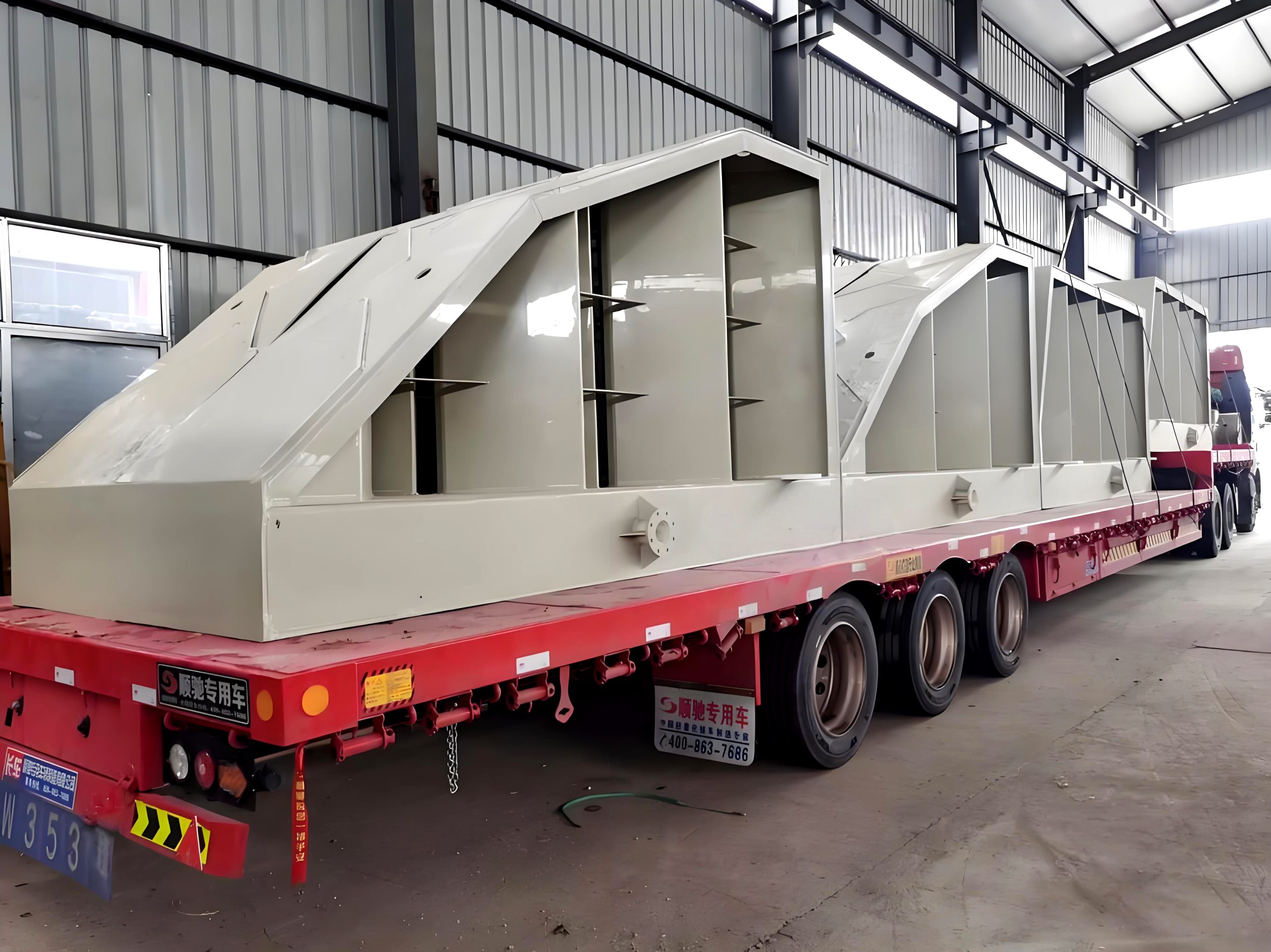
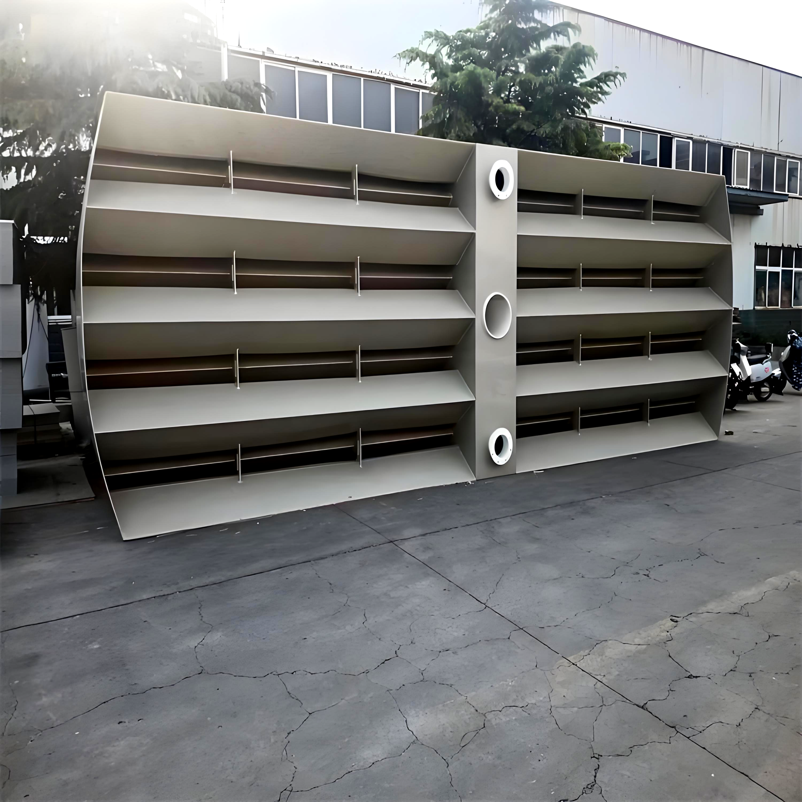
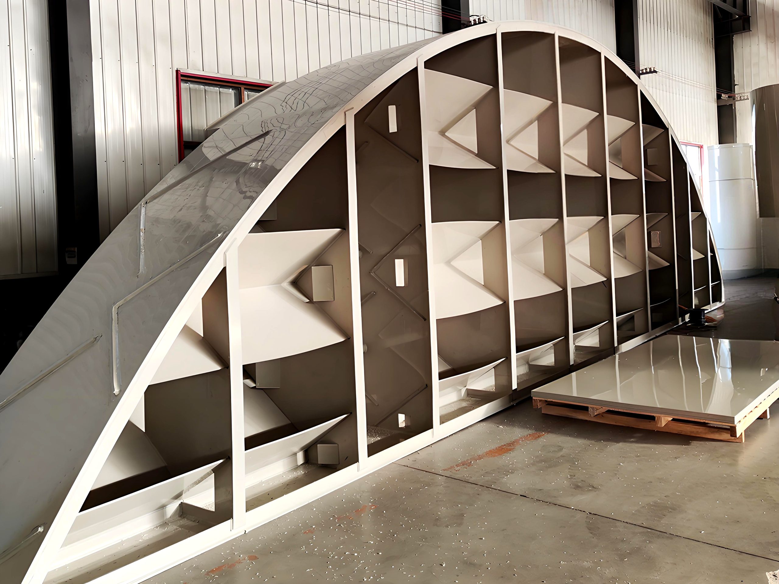
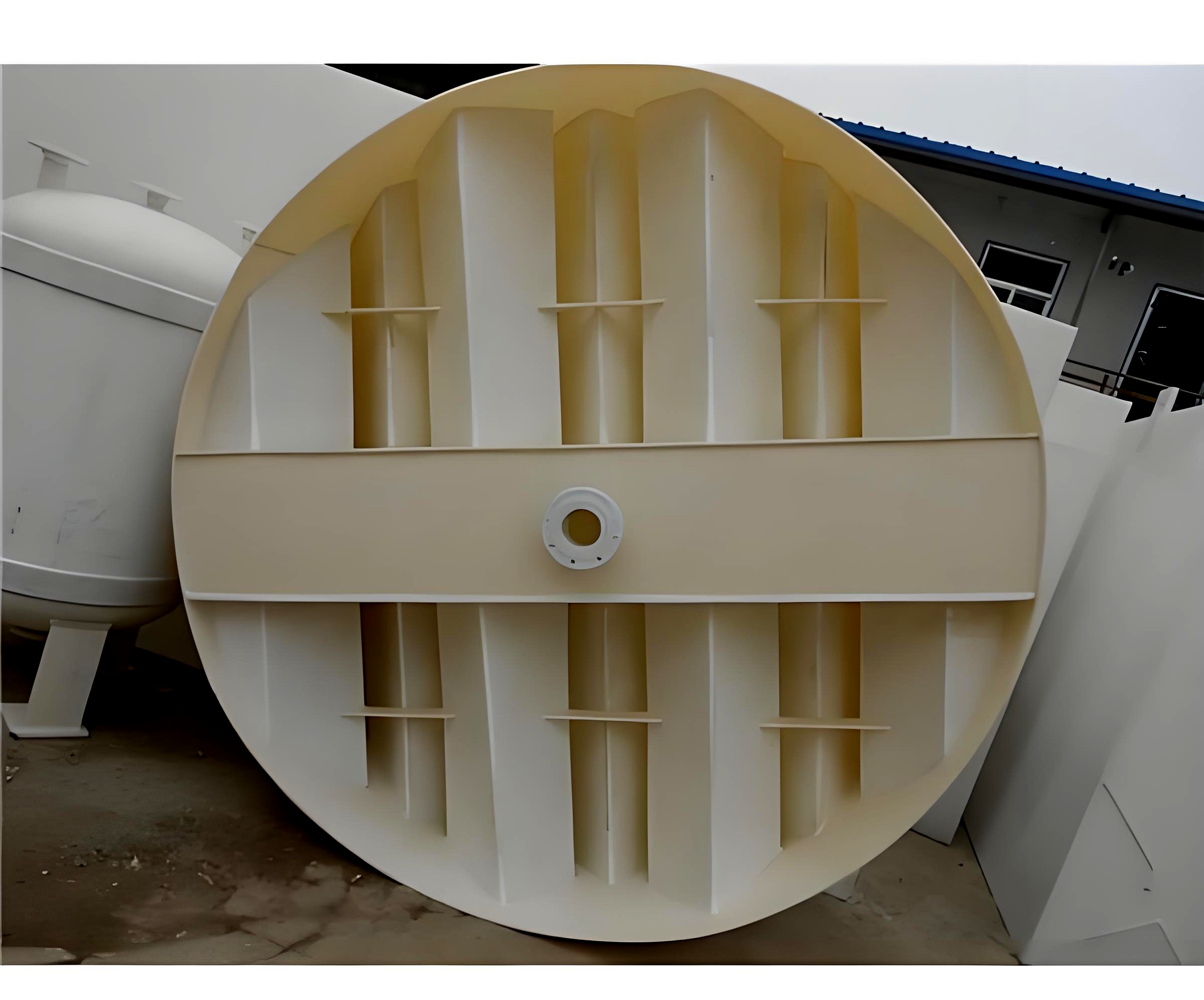
The three-phase separator is a key device specifically designed for efficient separation of the three phases (biogas, wastewater, and anaerobic sludge). It is typically installed at the top area of the UASB reactor. Its core structure usually consists of:
- Diversion plate/Reflection cone: Located at the bottom, it guides the ascending water flow (containing bubbles and sludge) to change direction.
- Air chamber/Collecting hood: Located at the top, it is used to collect the ascending biogas and is discharged through pipes.
- Sedimentation area/Separation area: The area between the diversion plate and the collecting hood, where the water flow slows down here, achieving separation of sludge and water.
- Return slit/Channel: The channel through which the clarified water after separation flows out of the reactor.
- Baffle/Overflow weir: Ensures that the clarified water flows out evenly and prevents gas or sludge from being carried out with the water.
In simple terms, its function is: To collect the biogas, discharge the clean water, and retain the precious sludge.
2. What is the Working Principle?
The remarkable feature of the three-phase separator lies in its ingenious utilization of physical principles such as gravitational sedimentation, bubble ascent, and change in hydraulic flow direction. It efficiently achieves the separation of three phases within a confined space.
- The mixed liquid rises: The mixture formed by sewage and anaerobic microorganisms (sludge particles) flows from the bottom of the reactor. Driven by the biogas (tiny bubbles) generated by the reaction, it flows upward from bottom to top.
- Impact and steering: The rising mixed liquid flows and impacts the guide plate (reflector cone) at the top. The flow direction is forced to change (usually from vertical upward to approximately horizontal or inclined).
- Bubble release and rising: When the flow direction changes and the flow velocity suddenly decreases, the biogas bubbles carrying the sludge particles are more likely to break free. The gas bubbles that have separated from the sludge move quickly upward vertically, passing through the liquid layer and entering the top gas chamber/collecting hood, and finally being collected and utilized.
- Sludge sedimentation: The sludge particles that lose the “lifting” effect of the gas bubbles have a density greater than water. In the relatively gentle sedimentation zone, they naturally sink by the force of gravity and return to the sludge bed layer at the bottom of the reactor, continuing to participate in the reaction.
- Clear water outflow: The relatively clear water after the gas and solid separation flows through the return slit or channel on the top of the separator, overflows the baffle or overflow weir, and flows smoothly out of the reactor and into the subsequent treatment unit or for discharge compliance.
Key point: The design of the baffle plate is of great significance. It creates a sudden change in flow velocity and a shift in flow direction, serving as the “trigger” that enables the separation of bubbles from sludge. At the same time, the settling area needs to maintain a relatively stable low flow rate environment to ensure the effective settling of sludge.
Related Products
Quick Contact
Please leave your email or phone number, We will reply as soon as possible